Power Pack
Updated May 25, 2023
It would be far easier to just buy one of the replica packs already available, but keeping in the spirit of the project, I will make my own.
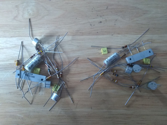
Before the 2008 recession I worked in electronics, and had grabbed a bunch of parts from old bins there for use in my pack. Recently (2019) I dug them out and found enough of the proper type of components to make 2 packs.
For the circuit board, I am laying out my own in kiCAD and may etch my own boards. I plan to use stain / tinted varnish to get the correct board color. I also plan to short the connections together in the phono jacks for pack insert detection instead of making an obvious copper trace between two jacks.
For references I am using drawings & materials produced by other club members as well as photos of the original Librescope boards that the pack was made from.
Board layout in process:

Once complete, I will provide a link to the files in case anyone wants to use them.
I had intended to build my frame by hand from plastic or metal, but have decided to 3D print a few of my robot parts. I have access to Solidworks modeling software at work, so I decided to make models of the frame, connectors, and transistor spacers. In the process, I discovered some new details and corrected what I believe are inaccuracies in available source material. I do not have access to an actual part but I do have some correct dimensions and believe that my models are reasonably close.
I went back through them recently and corrected the text fonts and tweaked the dimensions. Some details and text (such as pin numbers on connectors) will not show up unless you use a resin printer, but you may get "good enough" parts using an FDM printer.
Please go HERE for STL files and drawings of my frame, large and small connectors, and transistor spacer designs. They may be updated or removed at any time without notice.


A few of the details I came across and incorporated into my models:
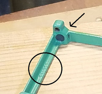
The frame has a number 1050189 on the underside of one of the rails.
Also, the rear part of the frame has a slope. This isn't apparent in photos of assembled units.
The back edge of the frame sits slightly above the circuit board, with a gap in-between.


In pictures of different Librescope modules, the mold cavity number is visible on the large connector.

There are round indents on the bottom of the frame at the small-connector end.